CUZIPLYFactory-direct plywood
Get a quote
APPLICATION GUIDETRAILERS · STAGES · STAIRS · PLATFORMS

Anti-Slip Plywood Flooring for Trailers, Stages, Stairs and Industrial Platforms

Specify anti-slip plywood as part of the complete floor: match the tread and overlay to users, footwear or wheels, then coordinate the core, 8–12% export moisture, bond, thickness, supports, joints, fasteners, sealed cuts, drainage, cleaning and test condition. This produces comparable quotations for trailer floors, stages, stairs, ramps and industrial platforms.

01 / Duty
Users + traffic
02 / Load
Distributed + dynamic
03 / Support
Centres + joints
04 / Exposure
Moisture + contamination
05 / Surface
Pattern + test requirement
06 / Service
Inspect + replace

Compare the available plywood families in the Product Catalogue.

OPERATING CONDITION INTAKE

Buyer inputs define the system before the panel.

Each row connects a buyer or designer input with the output needed to select panel construction, thickness, surface and installation details.

  1. 01

    Users and traffic

    Identify pedestrians, operators, passengers, maintenance staff and access restrictions. State footwear, direction of travel and whether users carry loads.

    Provided by
    Buyer / operator
    Specification output
    Traffic profile and access duty
  2. 02

    Distributed load

    Provide the design load from the responsible system designer, including the loaded area and applicable load combinations, so panel construction and support geometry can be matched to the deck.

    Provided by
    System designer
    Specification output
    Declared distributed-load case
  3. 03

    Concentrated and dynamic load

    State wheel, foot, caster, outrigger, impact or moving-load details, contact area, speed and repetition. Attach the vehicle or equipment specification where applicable.

    Provided by
    Buyer / system designer
    Specification output
    Point and dynamic load cases
  4. 04

    Support centres and joint support

    Send the frame drawing, support direction, centres, bearing width and every panel-joint position. Identify removable panels and local openings.

    Provided by
    System designer / fabricator
    Specification output
    Support and joint map
  5. 05

    Indoor/outdoor moisture and drainage

    Describe rain, wash water, condensation, standing-water risk, underside ventilation, drainage path and edge exposure.

    Provided by
    Buyer / project authority
    Specification output
    Exposure and drainage category
  6. 06

    Water, oil, mud, dust or cleaning contamination

    List foreseeable contaminants, frequency, cleaning chemistry, cleaning tools and acceptable shutdown time.

    Provided by
    Operator / maintenance team
    Specification output
    Contamination and cleaning profile
  7. 07

    Pedestrian, wheel and rolling-wear duty

    State traffic frequency, caster or tyre material, wheel diameter, axle loading input and turning or braking zones.

    Provided by
    Buyer / equipment responsible party
    Specification output
    Wear and rolling-traffic option
  8. 08

    Surface/test requirement

    Name the project method, operating condition and classification where specified. When the method is open, state the use, destination, footwear or wheel contact and expected contamination for a suitable test recommendation.

    Provided by
    Project authority / buyer
    Specification output
    Surface test specification
  9. 09

    Fixing, cut-outs, edges and transitions

    Provide fixing type, hole and cut-out positions, edge distance option, joint gap, nosing, threshold and transition details from the system drawing.

    Provided by
    Designer / installer
    Specification output
    Fabrication and installation detail set
  10. 10

    Inspection, cleaning and replacement plan

    Define who inspects, what conditions trigger escalation, how panels are isolated, and how a replaceable panel is removed without damaging the frame.

    Provided by
    Operator / asset responsible party
    Specification output
    Service and handover plan
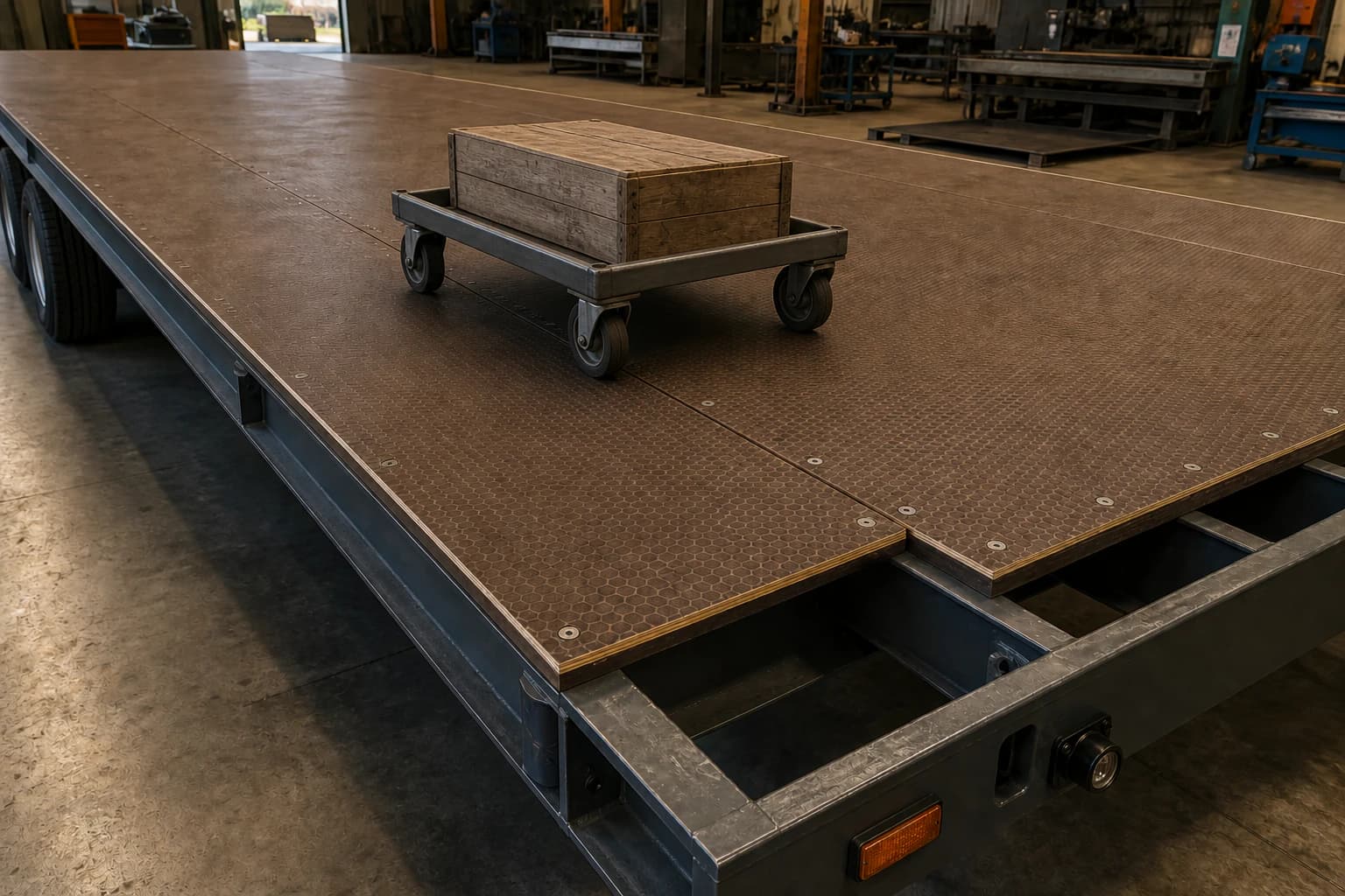
TRAILER & MOBILE DECK SYSTEM

Read panel, joint, support, fixing and wheel path together.

Patterned plywood trailer deck over steel cross-members with a supported joint, flush fasteners and a loaded platform trolley
Plywood in useTrailer deck reference showing a rolling load on a supported patterned-panel system; use the project drawing for actual geometry.
01 / Deck
Continuous patterned panel
02 / Support
Transverse steel members
03 / Joint
Bearing over frame
04 / Fastener
Flush controlled head
05 / Edge
Layered and sealed
06 / Duty
Caster load path
APPLICATION OPTIONS

Match the construction to the floor, traffic and service conditions.

Trailer, container, stage, stair, ramp and industrial floors place different demands on the substrate and surface. Container flooring follows the equipment manufacturer's structural, rolling, material, hygiene and repair specification.

01

Trailer floors

Primary duty
Vehicle deck carrying distributed cargo plus wheel, point and dynamic loads during travel and handling.
Critical input
Trailer drawing, support grid, axle and equipment load cases, fastening, edge exposure and drainage.
Suitable construction
Patterned anti-slip panel or structural substrate with a separately specified surface system.
Design responsibility
Trailer designer / body builder
Key risk
Local crushing, deflection, loose fasteners and water entry at perimeter details.
Quotation input
Attach trailer model, deck drawing, load cases and support centres.
02

Container/freight flooring option

Primary duty
Freight floor exposed to rolling cargo equipment, repair rules and responsible party-specific durability requirements.
Critical input
Container or equipment responsible party specification, repair standard, rolling-load option, material and hygiene requirements.
Suitable construction
Project-qualified freight-floor construction; patterned anti-slip is considered only when the responsible party specification permits it.
Design responsibility
Container/equipment responsible party and repair authority
Key risk
Assuming a tread pattern satisfies container structural, rolling-shear, material or repair requirements.
Quotation input
Provide equipment type, responsible party specification, repair context and required supporting documentation.
03

Stage decks

Primary duty
Modular performance or production deck carrying people, scenery and moving equipment.
Critical input
Stage-system frame, module connections, point loads, caster traffic, finish, indoor/outdoor exposure and replacement method.
Suitable construction
Patterned anti-slip panel for a qualified replaceable deck, or structural substrate with a project surface.
Design responsibility
Stage-system designer / rental operator
Key risk
Unsupported joints, uneven modules, surface wear and panel replacement that changes system behaviour.
Quotation input
Send stage system, module size, frame drawing, load input, caster duty and event exposure.
04

Temporary event flooring

Primary duty
Repeated assembly, pedestrian movement and temporary exposure across demountable floor modules.
Critical input
Sub-base, module support, assembly cycles, wet-use possibility, accessibility transitions and cleaning plan.
Suitable construction
Replaceable patterned modules or a specified temporary-floor system after support and transition review.
Design responsibility
Event-floor supplier / temporary works designer
Key risk
Trip edges, movement between modules, contamination-driven grip loss and handling damage.
Quotation input
State module system, sub-base, transition detail, assembly cycles and conditions.
05

Stairs and treads

Primary duty
Foot traffic over repeated nosing transitions where tread geometry and edge visibility affect safe movement.
Critical input
Stair geometry, support under each tread, nosing, environment, footwear and nominated slip option.
Suitable construction
Patterned tread panel or structural tread substrate with a project-selected surface and nosing.
Design responsibility
Building/project designer
Key risk
Unsupported tread edges, raised fixings, worn nosings and a surface class unrelated to the installed condition.
Quotation input
Provide stair drawing, tread support, nosing, destination code and surface requirement.
06

Ramps and landings

Primary duty
Pedestrian, wheelchair, trolley or equipment movement across an incline and level transition.
Critical input
Slope, landing layout, direction of travel, drainage, contamination, wheel duty and project accessibility requirement.
Suitable construction
Specified patterned or coated system validated for the nominated ramp condition.
Design responsibility
Access-system designer / project authority
Key risk
Water retention, abrupt transitions, wheel-induced wear and inappropriate extrapolation from a dry level test.
Quotation input
Send ramp gradient, landing geometry, user/wheel profile and wet-condition requirement.
07

Grandstands

Primary duty
Public circulation, seating access and temporary or permanent tiered-platform service.
Critical input
Grandstand system, aisle and stair layout, public-use classification, weather exposure and inspection regime.
Suitable construction
Structural substrate plus the surface system required by the responsible grandstand designer.
Design responsibility
Grandstand designer / venue operator
Key risk
Misaligned transitions, unsupported modules, public-access surface mismatch and delayed replacement.
Quotation input
Provide system supplier, aisle/tier drawing, use classification and maintenance plan.
08

Loading platforms and scaffolding decks

Primary duty
Work access and material handling where edge protection, openings and concentrated loads are controlled.
Critical input
Platform/scaffold system approval, support layout, access openings, handling loads, guardrail details and governing workplace option.
Suitable construction
System-approved structural substrate with specified anti-slip surface; panel selection follows the platform design.
Design responsibility
Temporary works or platform designer
Key risk
Substituting a generic panel into a proprietary or engineered system, edge breakage and unsecured access panels.
Quotation input
Attach platform system, support plan, access openings, duty and authority requirements.
09

Industrial walkways and service platforms

Primary duty
Routine operator and maintenance access near equipment, fluids, dust and service openings.
Critical input
Support grid, environment, contamination, cleaning, access-panel layout, guardrail interface and shutdown strategy.
Suitable construction
Patterned panel for managed service or structural substrate with a selected coating/overlay.
Design responsibility
Facility/project engineer
Key risk
Grip loss, swollen cut edges, loose access panels and concealed maintenance details.
Quotation input
Provide walkway drawing, contaminants, cleaning method, access panels and replacement strategy.
10

Utility cart / platform trolley decks

Primary duty
Small mobile deck carrying repeated caster, tool or component loads.
Critical input
Cart frame, caster spacing and material, concentrated load, turning, braking, deck attachment and edge protection.
Suitable construction
Patterned anti-slip panel or structural substrate selected against the cart frame and wheel contact.
Design responsibility
Cart or trolley manufacturer
Key risk
Local crushing at caster paths, edge impacts, fastener pull-through and panel/frame mismatch.
Quotation input
Send cart drawing, caster data, load case, deck fixing and expected cycles.
THREE CONSTRUCTION OPTION

Choose the substrate and walking surface as one compatible system.

A

Patterned Anti-Slip Plywood

Best fit
Best for supported walking or rolling surfaces where the buyer can define contamination, wear, supports, edge sealing and the required slip-test condition.
Surface
Wire-mesh, hexagonal or another approved pattern tied to the exact overlay and test specimen.
Panel / substrate
Cross-laminated plywood construction selected against the system support and load brief, normally supplied at 8–12% moisture for the stated export construction.
Load and documents
System designer confirms installed loads; panel we provide the agreed product specification and test documents.
Moisture and edges
Factory edge sealing plus compatible resealing of site cuts, holes and exposed edges, coordinated with drainage and underside ventilation.
Wear and wheel duty
Pattern, overlay, caster or tyre contact, turning zones and cleaning process are reviewed together.
Testing
Slip and wear supporting documentation is tied to the ordered surface, conditioning method and acceptance endpoint.
Selection guidance
Use this option when a patterned phenolic panel meets the stated load, support, exposure and maintenance brief.
View Anti-Slip Plywood
B

Structural Plywood + Specified Surface

Best fit
Best when declared structural properties, a structural grade or an engineer's design leads the floor-system decision.
Surface
Project coating, bonded covering, aggregate system or specified anti-slip finish selected for the operating condition.
Panel / substrate
Structural plywood substrate with declared properties and traceability matching the design option.
Load and documents
Responsible engineer or project authority confirms the installed structural design and connection checks.
Moisture and edges
Substrate exposure class, coating compatibility, perimeter, joints and penetrations are detailed as one system.
Wear and wheel duty
Surface supplier and project responsible party define wear, repair and renewal criteria.
Testing
Structural substrate documents, surface test results and any installed-system test are recorded by their respective scopes.
Selection guidance
Use this option where the engineered substrate and separately specified walking surface have distinct performance requirements.
View Structural Plywood
C

Film-Faced / Project overlay options

Best fit
Best when a film-faced or overlay-ready substrate receives a named patterned film, applied overlay or coating designed for the duty.
Surface
Smooth film-faced plywood serves formwork; the ordered patterned film, applied overlay or complete coating system defines the walking-surface evaluation.
Panel / substrate
Film-faced or overlay-ready plywood construction matched to bonding, fabrication and exposure inputs.
Load and documents
Project designer confirms installed capacity; surface-system responsible party provides compatibility and use supporting documentation.
Moisture and edges
The design combines face continuity with separately sealed site cuts, holes, joints, underside details and drainage paths.
Wear and wheel duty
Wear and wheel duty are evaluated for the selected surface system and its maintenance method.
Testing
Testing uses the exact surface, conditioning and service condition named in the project specification.
Selection guidance
Use this option for a purpose-designed overlay system whose substrate, surface and installation details are specified together.
View Film Faced Plywood
SERVICE RISK GUIDE

Prevent common floor problems through design, installation and inspection.

FailureCauseVisible signPrevention inputInspection pointReplacement trigger
Excessive deflectionA mismatch between panel construction, thickness, support centres and the declared load case.Visible sag, bounce, cracked finish or changing joint levels.Approved system drawing, support centres, load inputs and design responsibility before panel release.Check level, movement and support contact during installation and service.Escalate when movement, damage or the project limit is exceeded; the responsible designer decides isolation or replacement.
Local crushing from point or wheel loadsSmall contact areas, turning wheels or outriggers overload the panel or support interface.Dents, crushed overlay, soft spots, fastener dish or local core damage.Provide wheel/contact geometry, dynamic case, load path and local support details.Inspect known turning, braking, outrigger and transfer zones.Isolate a locally damaged panel when integrity, surface continuity or fixing retention is uncertain.
Unsupported joints or edge breakageA panel seam or cut edge falls between supports or has inadequate bearing.Stepped joint, chipped edge, flexing seam or split face around the joint.Place every joint on an adequate support and coordinate openings before cutting.Verify joint-to-support alignment before fixing and after module assembly.Replace the panel or introduce an approved support change when bearing falls outside the project requirement.
Fastener loosening, pull-through or raised headsWrong fastener/head, poor edge distance, moving substrate, over-driving or repeated vibration.Proud head, enlarged hole, fretting, loose panel or pull-through dish.System-specific fastener, head, pilot, edge-distance and substrate option.Record head condition, movement and hole damage at service checks.Use the approved repair detail, with panel replacement when hole or core condition falls outside the connection requirement.
Water entry and edge swellingUnsealed cuts, damaged edge coating, standing water, exposed holes or poor drainage.Darkened edge, raised plies, swelling, coating cracks or joint misalignment.Seal factory edges and reseal site cuts/holes; detail drainage and underside ventilation.Inspect perimeter, penetrations, low points and cut-outs after wet exposure.Isolate when swelling changes level, fixing retention or structural condition beyond the project acceptance rule.
Overlay wear, damage or separationAbrasive traffic, incompatible cleaning, impact, moisture entry or substrate movement.Polished path, exposed substrate, tear, blister, lifting or local delamination.Match overlay and substrate to traffic, contamination and cleaning; protect panels before installation.Compare wear zones with the approved reference and record local damage.Renew or replace when the surface options, substrate protection or project acceptance requirement is no longer met.
Grip loss from wear or contaminationWater, oil, grease, mud, dust, aggregate or residue changes contact at the surface.Visible film, packed tread, polished traffic line or cleaning residue.Define expected contaminants, drainage, cleaning process and relevant test condition.Inspect and, where required, re-evaluate the actual service condition alongside the new-surface reference.Escalate after cleaning when the measured surface outcome remains outside the project requirement.
Trip edge at joints, transitions or damaged panelsDifferential movement, poor transition detail, swelling, loose fixing or impact damage.Raised lip, widened gap, loose nosing or abrupt height change.Coordinate joint support, tolerances, nosing, thresholds, drainage and replaceable-panel geometry.Walk the option and check transitions under the operating condition.Isolate promptly when the edge creates an unacceptable access hazard; repair or replace to the approved detail.
Handling or packing damage before installationWet packs, uneven support, strap damage, forklift impact or dragging panels.Bent corners, crushed edge, face scoring, pack distortion or moisture staining.Use dry level supports, protected corners, controlled straps and written lifting and handling points.Compare arrival condition with the reference before panels enter fabrication.Segregate visible damage before fabrication and agree the repair or replacement option.

Prevent arrival damage through the Export Process.

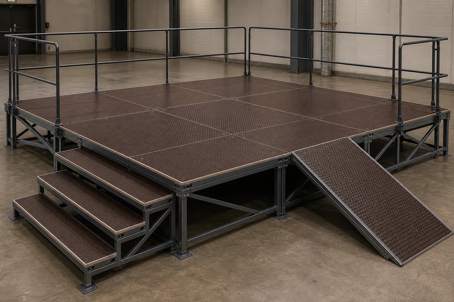
STAGE, STAIR & RAMP ASSEMBLY

Modules, transitions and guardrails belong to one support system.

Modular steel stage with fully supported patterned plywood deck panels, three stair treads, a ramp and frame-mounted guardrails
Plywood in useModular stage reference with joints carried by the frame and separate stair/ramp transitions; project geometry controls the final assembly.
SUPPORT, JOINT & FASTENER SEQUENCE

Coordinate geometry, fabrication and installation in eight steps.

  1. 01

    Confirm system drawing and responsible designer

    Freeze the drawing revision, intended use, design authority and interfaces before a panel is named.

  2. 02

    Fix support centres and joint positions

    Place every full panel, seam, opening and removable section on the approved support geometry.

  3. 03

    Check concentrated and dynamic load path

    Trace wheels, casters, outriggers, moving equipment and transfer points through panel, fixing and frame.

  4. 04

    Select panel construction and thickness for that design

    Compare Anti-Slip, Structural or project-overlay options only after the system inputs are explicit.

  5. 05

    Select fastener type, head and edge-distance option

    The designer/fabricator confirms substrate, corrosion, vibration, pilot and replacement requirements.

  6. 06

    Seal factory edges, site cuts and holes

    Carry the compatible sealing system through fabrication and record repairs before installation.

  7. 07

    Detail drainage, transitions, nosings and replaceable panels

    Resolve water path, trip edges, access and removal without improvising on site.

  8. 08

    Record installed inspection and handover

    Verify supports, joints, fasteners, edges, surface condition and maintenance ownership against the approved file.

Use Plywood Sizes & Thicknesses after the support and handling requirements are known.

SURFACE CONDITION & TEST SELECTOR

Specify the surface for the operating condition and maintenance method.

ConditionSurface decisionTest or documentCleaningWear / retestResult scope
Dry pedestrian trafficChoose a cleanable tread or specified coating compatible with footwear and option geometry.Use the named dry-condition method and class where the project requires one.Remove fine dust and polish residue so the intended contact surface remains available.Reassess when traffic polishing or use changes.The recorded class follows the tested surface, method and condition.
Rain/wet pedestrian trafficCoordinate tread, drainage, slope, transitions and edge protection.Use the project-nominated wet condition and method.Keep drains and tread relief clear and maintain the intended water path.Review after wear, repairs or drainage changes.Wet-condition results are recorded separately from dry-condition results.
Oil/grease exposureCombine containment, rapid removal and a chemically compatible surface.Use a project-specific contaminated-condition assessment where required.Define degreaser compatibility, dwell time, rinse and residue removal.Re-evaluate after repeated chemical cleaning or visible polishing.The operating plan controls oil exposure, cleanup and access restoration.
Mud/dust/aggregate contaminationSelect a tread geometry that releases the expected material within the planned maintenance process.Condition the specimen with representative contamination where testing is required.Define sweeping, wash-down or extraction that preserves the overlay.Inspect packed texture and abrasive wear zones.Tread depth, cleanability and footwear or wheel contact are evaluated together.
Repeated trolley/wheel trafficMatch overlay, core, support and fastener detail to wheel contact and turning.Combine the rolling or wear option with installed-load verification.Remove hard debris that increases abrasion or wheel shock.Track wheel paths and turning zones.Rolling-load capacity follows the supported panel system and declared wheel contact.
Temporary stage/event useCoordinate module joints, transitions, handling cycles and replaceable deck panels.Combine the panel result with temporary-works, venue and event acceptance.Use a repeatable turnaround inspection and cleaning record.Check after transport, assembly and wet events.Complete-stage acceptance combines the deck, frame, connections, transitions and operating plan.
Stair/ramp transitionCoordinate tread, nosing, incline, landing and visibility with the project design.Destination access/code option and named surface test.Keep nosings, transitions and drainage clear.Reassess when nosing, coating or traffic path changes.Inclined and installed access options use the test condition relevant to their geometry and service.
Cleaning chemical/processConfirm chemical, temperature, dwell time and mechanical cleaning compatibility.Agree the compatibility check and post-clean surface condition.Document dilution, tools, rinse and residue control.Inspect after process change or surface softening or dulling.Post-clean inspection confirms the surface and bond condition after the selected process.
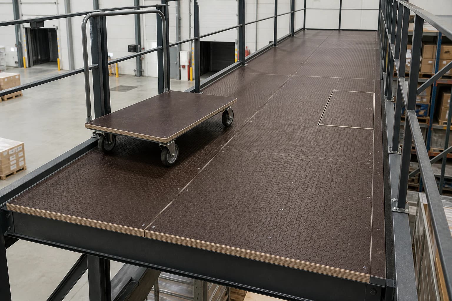
INDUSTRIAL WALKWAY & LOADING PLATFORM

Rolling paths, access panels and edge control stay inspectable.

Industrial service walkway with supported patterned plywood panels, flush fasteners, a maintenance hatch and four-caster trolley
Plywood in useIndustrial walkway reference with supported joints, visible fixing heads, a removable access hatch and a four-caster trolley.
TEST & DOCUMENT OPTIONS

Match each requested result to the ordered surface and construction.

01

Slip surface options

Available by order
What it answers
How does the exact new or installed surface behave under the nominated condition?
Method or authority
EN 16165, AS 4586 or the project-nominated surface method and condition.
Test specimen / input
Exact pattern or finish, conditioning, direction and contamination state.
Who confirms it
Project authority selects the requirement; supplier and laboratory prepare the agreed specimen.
Quotation scope
The report identifies the tested surface, method, conditioning and result so it can be matched directly to the ordered construction.
02

Wear / rolling traffic option

Project-specific
What it answers
How does the surface and panel respond to defined abrasion, wheels or repeated traffic?
Method or authority
Project wear method, rolling-load protocol or responsible party-specific acceptance plan.
Test specimen / input
Exact overlay, core, wheel/contact data, cycles, support and acceptance criteria.
Who confirms it
Equipment/system responsible party defines duty; supplier and test party agree the specimen.
Quotation scope
Rolling and wear performance is recorded against its own wheel, cycle, support and acceptance conditions.
03

Panel bond / moisture option

Available by order
What it answers
How is the plywood bond and edge system matched to the specified exposure?
Method or authority
EN 314-2 or destination product-bond specifications plus edge and conditioning plan.
Test specimen / input
Exact plywood construction, bond, overlay, edge seal, holes and exposure class.
Who confirms it
we provide product documents; buyer confirms exposure and acceptance requirements.
Quotation scope
The order can pair bond documents with 8–12% export moisture, factory edge sealing and the specified site-cut treatment.
04

Structural substrate / installed load option

Project-specific
What it answers
Can the complete supported system carry declared loads and connections?
Method or authority
AS/NZS 2269 where applicable, project structural specification, engineered calculation or full-system test.
Test specimen / input
Declared substrate, thickness, span or supports, joints, fixings and actual load cases.
Who confirms it
Responsible engineer or system designer confirms the installed design.
Quotation scope
The project requirements records the selected thickness, support geometry, connections and declared load cases.
05

Destination building, workplace, vehicle or project requirements

Configured by destination
What it answers
Which legal, contractual, workplace, vehicle or responsible party rules govern the installed use?
Method or authority
NCC or AS 1657 for relevant Australian projects, vehicle or container-responsible party specification, workplace rules or country and project documents.
Test specimen / input
Named destination, authority, building or vehicle type, use and system specification.
Who confirms it
Importer, project authority, vehicle responsible party or employer confirms applicability.
Quotation scope
Country, application and responsible authority determine the document list included with the quotation and order.
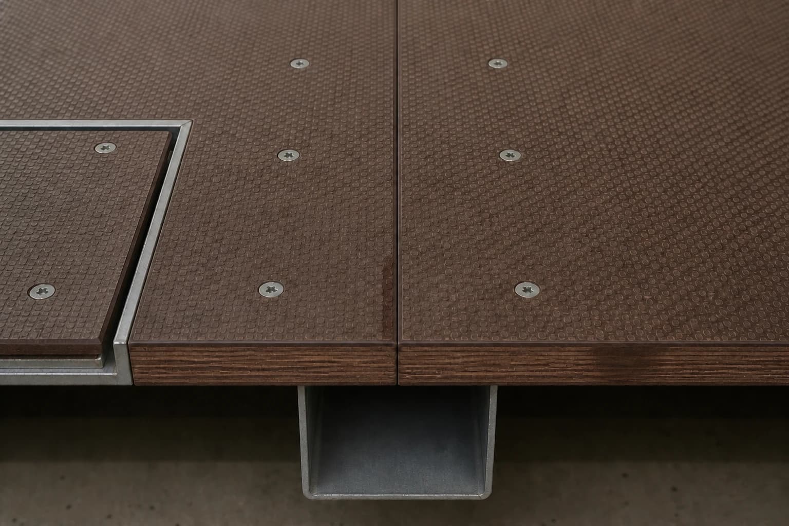
JOINT, EDGE, FASTENER & MAINTENANCE

A serviceable joint keeps bearing, heads, film and resealed edges visible.

Close-up of two level anti-slip plywood panels supported at a uniform joint, with flush fasteners, thin patterned film and dark resin-sealed cut edges
Material StudyClose application detail of two level panels supported over steel; the thin surface film, layered edges, flush heads and resealed cut patch remain inspectable.
INSPECTION, CLEANING, MAINTENANCE & REPLACEMENT

Records keep the approved system legible in service.

  1. 01

    Pre-installation reference and damage check

    Confirm lot, approved surface reference, dimensions, edge seal, pack condition and handling damage before fabrication.

    Arrival and inspection and approval records
  2. 02

    Installed support, joint and fastener inspection

    Verify full bearing, joint location, level, fastening, transitions and access-panel security against the drawing.

    Installation handover
  3. 03

    Routine contamination and cleaning control

    Remove water, oil, mud, dust and residue with the agreed process; document recurring contamination sources.

    Routine service log
  4. 04

    Edge, hole and seal inspection

    Check perimeter, cut-outs, penetrations and repaired areas for seal damage, swelling or exposed core.

    Edge and penetration record
  5. 05

    Wear/slip re-evaluation when use or condition changes

    Escalate when traffic, wheel duty, cleaning, contamination, slope or surface condition departs from the approved brief.

    Change and re-evaluation record
  6. 06

    Panel isolation and replacement trigger

    Use the project's criteria to isolate a damaged area and replace the panel or surface system without altering the frame or connection detail.

    Disposition and replacement record

Surface contamination, wear, loose fasteners, joint-level changes, water entry and local damage can change the result. The project maintenance plan links isolation and replacement to the actual inspected condition.

Continue to Quality & Inspection for the shared lot and inspection framework.

DESTINATION REQUIREMENTS

Match documents to the country, project and responsible authority.

MarketPriorityDestination inputApplication authorityTest / document triggerConfirmation
AustraliaTier 1State, building/vehicle type and importer/project requirements.Project designer, importer and relevant building/workplace/vehicle authority.NCC, AS 4586, AS 1657 and AS/NZS 2269 are separate conditional options.Importer/project confirms applicability and exact supporting documentation before release.
Middle EastTier 1Country, emirate/municipality or client specification and use.Importer, consultant, contractor or vehicle/system responsible party.Project slip, structural, fire, documentation or climate/exposure requirements as nominated.Buyer confirms governing documents and acceptance criteria.
Central AsiaTier 1Country, customs/use classification and project specification.Importer, project designer or equipment responsible party.Country conformity, bond/exposure and project test methods.Importer confirms language, documents and authority.
Latin AmericaTier 1Country, port, use, project standard and language.Importer, consultant, vehicle/system responsible party or workplace authority.Country/project slip, structural, customs and documentation option.Importer confirms Spanish/Portuguese terminology and legal requirements.
AfricaTier 2Country, project, vehicle/platform type and importer requirements.Importer and named project/system authority.Country-specific conformity, exposure, supporting documentation and documentation option.The importer confirms the requirements for the named country and project.

Destination briefs: Australia and Middle East.

QUOTATION CHECKLIST

Send the floor drawing and operating conditions for a comparable quotation.

  1. 01Country and destination
  2. 02Use case
  3. 03System drawing/platform dimensions
  4. 04Distributed load
  5. 05Concentrated/dynamic or wheel load
  6. 06Support centres and joint positions
  7. 07Pedestrian/wheel traffic
  8. 08Indoor/outdoor exposure
  9. 09Water/oil/mud/dust/cleaning condition
  10. 10Surface pattern or recommendation request
  11. 11Required slip/wear/bond/structural option
  12. 12Panel size and thickness or recommendation request
  13. 13Core/bond specifications or recommendation request
  14. 14Fastener and edge/cut-out details
  15. 15Inspection/maintenance expectation
  16. 16Quantity and packing
  17. 17Required delivery date

Product: Anti-Slip Plywood · Destination: specified with the enquiry · Incoterm: Recommended with the quotation after destination and shipment details are confirmed.

Prefer a separate enquiry? Build an RFQ.

APPLICATION QUESTIONS

Direct answers for specification, installation and service.

DECISION QUESTIONS

Before the purchase order

Choose the right specification.

What plywood is used for trailer floors?

Trailer plywood is selected from the complete vehicle-deck specification. The body builder or responsible designer provides support centres, joints, distributed and concentrated loads, wheel or equipment contact, fastening, drainage and edge exposure. A patterned anti-slip panel can suit a defined deck, while a structural substrate with a separate surface system may be preferable when declared structural properties govern. The quotation should therefore include the trailer drawing and load cases.

Is anti-slip plywood suitable for container flooring?

Container and freight floors are specified to the equipment responsible party's structural, rolling-load, bond, durability, material, hygiene and repair requirements. Send the equipment type, responsible party or repair specification, support layout, rolling-load option and required approvals. We can then compare a project-qualified freight-floor construction with the patterned anti-slip option and quote the construction that matches the responsible party specification.

How does film faced plywood differ from an anti-slip floor?

Standard smooth film faced plywood is designed around concrete release and surface finish. An anti-slip floor uses a named patterned film, coating or complete surface system selected for the actual pedestrian or wheel condition. The quotation combines that surface with the required core, bond, moisture range, sealed edges, supported joints, load path and maintenance method.

How should plywood be selected for stages and temporary event decks?

Start with the proprietary or engineered stage frame, module connections, support positions, point loads, caster traffic, indoor or outdoor exposure, transitions, assembly cycles and replacement method. Select the surface for those conditions and combine the panel result with the stage frame, connections and venue acceptance. Any deck substitution is then confirmed by the stage responsible party or designer.

Can anti-slip plywood be used for stairs and ramps?

Yes, where the project designer defines tread support, stair or ramp geometry, nosings, landings, transitions, drainage, users and the destination requirement. Specify slip testing for the relevant dry or wet condition, direction and incline. The completed access option then combines the selected surface with its support, transitions and maintenance plan.

What thickness or support spacing is required?

Thickness and support spacing are selected together from the panel construction, distributed load, point or wheel contact, support direction and centres, joint bearing, fixings, openings and exposure. Send the system drawing and load cases so the panel options can be prepared; the responsible designer then confirms the final supported arrangement for the platform or vehicle deck.

How should joints, fasteners, cut edges and holes be detailed?

Every joint should land on an adequate support in the approved drawing. Fastener type, head, pilot and edge-distance option must match the substrate, vibration, corrosion and replacement needs. Factory edges, site cuts and drilled holes receive the compatible seal before exposure. Nosings, thresholds, drainage and removable panels are resolved before fabrication rather than improvised during installation.

How is slip resistance specified and tested?

Name the relevant method, test condition, specimen, conditioning and required classification or acceptance rule. EN 16165 or AS 4586 may be possible options when triggered, but the project authority decides applicability. New-surface testing, installed-surface measurement, wear evaluation and the complete load-bearing system answer different questions and should not be merged into one claim.

How should the surface be cleaned, inspected and replaced?

The operator records expected water, oil, mud, dust and cleaning chemistry, then inspects traffic paths, joints, fasteners, transitions, cut edges and seals. Changes in contamination, wear, use or cleaning trigger re-evaluation. The project inspection plan sets the isolation and replacement criteria while preserving the specified support and connection detail.

What information is required for a project quotation?

Send country and destination, use, system drawing, platform dimensions, distributed and point or wheel loads, support and joint positions, traffic, exposure, contaminants, cleaning method, preferred surface, required test documents, panel size and thickness, core and bond preference, fixing and edge details, maintenance expectation, quantity, packing and required date. Where a field is open, describe the operating condition and our team will recommend a suitable option and Incoterm.

Plywood enquiry

Tell us what you need.

Attach the system drawing and state country, use, loads, support centres and joints, traffic, exposure, contamination, surface/test methods, size and thickness, core/bond specifications, fixing and cut-edge details, maintenance, quantity, packing and required date. Mark any undecided field for our recommendation, including the suitable Incoterm.

CHAT WITH CUZI PLY

By sending this request, you allow CUZI PLY to use the submitted details to respond. Read the Privacy Policy.