Payload type
Name the equipment, its function and every accessory that must travel in the same case.
CUZI PLY supplies flight case plywood for touring audio, lighting, broadcast, instruments, precision equipment, service tools and reusable protective enclosures. Lightweight poplar, birch-faced combi, all-birch high-ply, HPL-faced and phenolic-film constructions can be matched to the payload, case span, target empty mass and surface duty. The panel’s actual thickness must suit the aluminium extrusion slot, while dense local support, backing plates and clean machining protect handles, latches, hinges, casters and rack interfaces. Send the payload drawing, loaded mass, case envelope, hardware schedule and transport lanes to receive a practical construction and quotation.
| Application | Typical payload | Handling method | Panel priority | Hardware / cushioning | Project check |
|---|---|---|---|---|---|
| Touring audio, lighting and AV road cases | Mixers, luminaires, speakers and control equipment | Frequent rolling, loading docks and vehicle transfers | Panel mass, corner continuity and replaceable interfaces | Casters, handles, latches and dense local reinforcement; shaped cushioning where required | Loaded first article, closure, rolling and nominated option checks |
| Musical instruments and backline equipment | Keyboards, amplifiers and protected instrument assemblies | Manual lifts, ramps, backstage moves and repeated opening | Low empty mass with durable edges and reinforced hardware zones | Instrument keep-outs, soft-contact inserts and consistent lid clearance | Fit, orientation, carry observation and post-transport inspection |
| Broadcast, camera and media systems | Camera bodies, lenses, monitors and field production kits | Vehicle, hand-carry and frequent field access | Balanced shell stiffness, cleanable surface and organised accessories | Removable inserts, separated small parts and service access | Inventory, fit, closure and representative handling-option check |
| Precision instruments and metrology equipment | Neutral gauges, optical benches and measurement systems | Moves between laboratory, service and calibration sites | Stable panel interfaces and a documented COG | No-contact zones, repeatable fit and condition-aware cushioning | Loaded fit, conditioning and method selected for the real option |
| Medical and laboratory non-sterile equipment | Non-sterile analysers, training equipment and service modules | Facility and transport handling | Cleanable case architecture and traceable replaceable components | Material compatibility, fit, segregation and documented cleaning option | Cleaning compatibility, payload fit and transport-option checks |
| Aerospace and airline repairable components | Repairable units and airline supplies named by a project | Airline logistics with traceable service records | Project-specified construction and maintainable interfaces | Use an ATA option when the customer specifies the applicable item and container scope | Project version, sample case, maintenance record and specified tests |
| Trade-show, display and demonstration equipment | Demonstration units, sample assemblies and portable display systems | Road transport, venue handling and repeated presentation | Appearance, manageable mass and fast service access | Replaceable finish panels, accessory pockets and protected visible faces | Loaded handling, closure, appearance and inventory check |
| Tools, controls and mobile service kits | Diagnostic tools, controllers and field service modules | Vehicle storage, workshop transfer and frequent component retrieval | Robust interfaces, labelled positions and maintainable compartments | Tool restraint, loose-part control and lid/door durability | Inventory, fit, closure and repeated-use inspection |
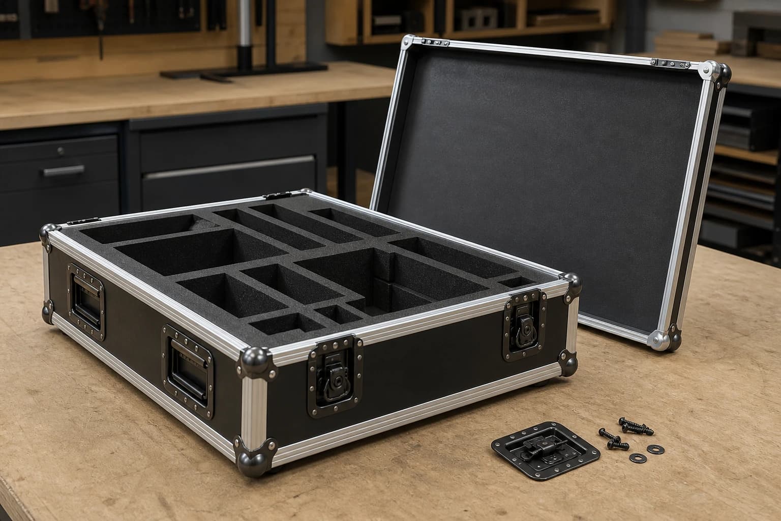
Actual thickness is selected with the payload, span, case envelope, extrusion slot, hardware reinforcement and loaded handling conditions.
| Panel construction | Best suited to | Weight / stiffness | Surface specification | Hardware and machining check |
|---|---|---|---|---|
| Lightweight poplar with ordered PVC/laminate finishOpen Poplar Plywood | Frequent handling where lower empty-case mass is important | Lower density can reduce shell mass while the chosen thickness, span and reinforcement provide the required stiffness | Specify PVC or laminate, reverse-face balance, edge closure and repair compatibility | Check the actual extrusion slot, fastener backing and impact-prone zones on a representative sample |
| Birch-faced balanced/combi core optionOpen Birch Plywood | A birch appearance and balanced cost/stiffness option are required | Face species is separated from the internal core statement | Confirm finish adhesion, balance and exposed-edge treatment | Inspect core reveal, hole quality and local reinforcement |
| All-birch / higher-ply high-duty optionOpen Birch Plywood | Stiffness, dense multiply edges and demanding interfaces lead | Higher ply count may support fine machining and local hardware zones | Confirm surface, edge, moisture and repair option | Machine and assemble the exact high-ply build |
| HPL-faced plywood optionOpen HPL Plywood | Wear, cleaning or decorative laminate leads the brief | Panel mass, laminate balance and substrate remain explicit | Specify HPL face/back system, edge closure and repair method | Check machining, adhesive, rivet/screw zones and extrusion fit |
| Phenolic / film-faced plywood optionOpen Film Faced Plywood | A durable, cleanable film surface suits the use and repair plan | Film and core are specified together with actual thickness | Confirm face texture, cut-edge sealing and patch scope | Inspect machining, film damage and hardware seating |
| Packing Plywood / cut-component option when panel procurement and cost lead the briefOpen Packing Plywood | The buyer needs panel or cut-part supply before case assembly | Construction and price are handled in the product file | Specify surface and edge protection for the case maker | Case maker validates hardware and complete shell |
| Component | Information to provide | Panel / interface requirement | Sample check |
|---|---|---|---|
| Aluminium edge extrusion | Name the extrusion profile, slot width, wall thickness, supplied length and intended corner-joint method. | Match measured panel thickness and prepared edge to insertion depth, grip, end joint and compatible edge sealing. | Trial a straight run, corner and end joint; inspect insertion depth, clamp, clearance and damage to the plywood edge. |
| Lid / base mating extrusion | Specify the paired lid/base profiles, closing direction, compression target and any nominated seal arrangement. | Keep upper and lower profiles coaxial around the perimeter, with compatible corner closures and latch keeper locations. | Open and close the complete perimeter repeatedly while measuring joint gap, corner seating and compression uniformity. |
| Ball corners and corner braces | Provide corner radius, panel-corner geometry, extrusion intersection and the selected corner/bracing hole pattern. | Maintain flat seating, practical edge distance and rear support without colliding with adjacent latches, hinges or profiles. | Assemble a representative corner and inspect face contact, hole position, profile convergence and reverse-side bearing. |
| Recessed butterfly latches | State latch model, cup depth, keeper position, required closing action and clear operating space around the recess. | Control the opening, edge distance, backing and relationship between latch, keeper and lid/base mating extrusion. | Open and close the complete joint repeatedly, checking hand clearance, keeper engagement and local shell distortion. |
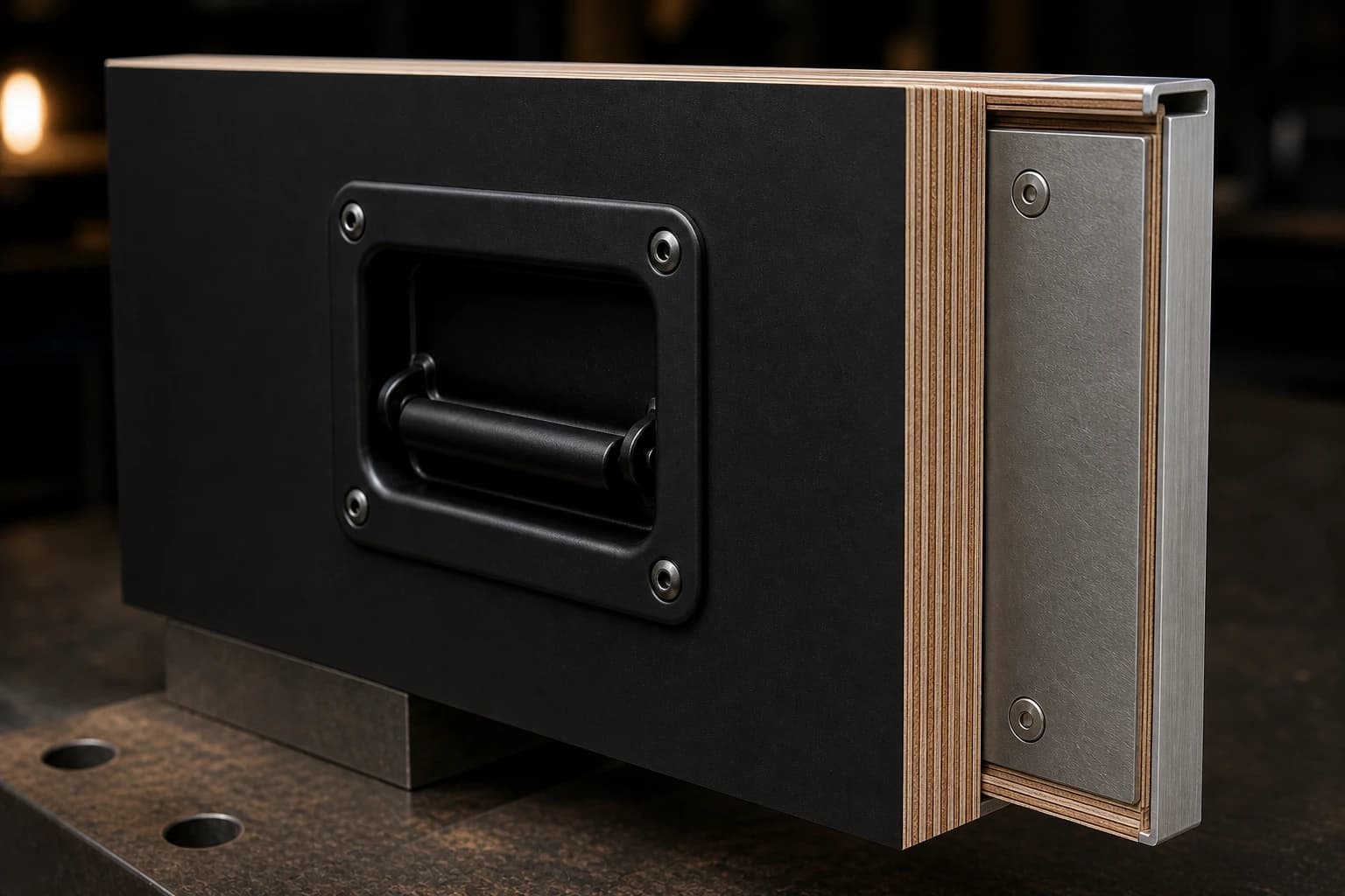
| Recessed handles | Give loaded mass, centre of gravity, lift direction, handle count/location, cup depth and available hand clearance. | Keep continuous plywood around the opening and specify a backing plate or large washers against local crushing. | Observe the real or representative loaded lift, including grip access, shell deflection, fastener seating and balance. |
| Hinges and lid stays | State lid mass, opening angle, hold-open position, hinge/stay type and the project service-cycle requirement. | Support hinge and stay fixings while controlling lid twist, over-travel, closing alignment and pinch zones. | Cycle the fully assembled lid through opening, hold and closure while observing fasteners, stays and panel deflection. |
| Caster boards and casters | Supply loaded mass, wheel diameter, mounting-plate pattern, floor type, thresholds, ramps, turns and braking needs. | Transfer wheel reactions through the caster board into the base frame and shell without face-only point loading. | Run the loaded first article straight, through turns, across the nominated obstacle and under braking observation. |
| Stacking dishes, feet and mating points | Identify the exact case combination, orientation and storage/transport condition permitted for stacking. | Align upper and lower mating points with local frame support so the approved pair remains stable and seated. | Assemble only the nominated loaded combination and inspect engagement, support, rocking and safe separation. |
| Rack rails and internal mounts | Provide equipment fixing points, rack format, payload centre of gravity, connector access and service-removal sequence. | Carry equipment load through the nominated internal frame and reinforced interfaces rather than decorative shell faces. | Install and remove the payload while checking mounting alignment, clearance, connector access and local movement. |
| Rivet / screw / washer / backing interface | Name fastener material, diameter, grip range, head form, washer/backing geometry and corrosion compatibility. | Control hole diameter, edge distance, veneer damage, reverse access and the installed rivet or torque condition. | Build and section the actual panel-fastener coupon, then inspect flange, bore, plies, backing and installed seating. |
| Removable lids, doors and service panels | Define removal frequency, orientation, retainers, closure/seal option and the space needed for the real service action. | Protect repeat-location edges and coordinate hinges, latches, cables and access openings without weakening the frame. | Repeat the actual removal, refit, closure and service sequence while checking alignment and edge condition. |
| Labels, tracking and replaceable service parts | Set asset identifier, label material/location, scan method, replaceable-parts list and authorised repair responsibility. | Keep labels and their holes or adhesives away from critical structure and preserve access to service hardware. | Check readability, adhesion, scanning, part removal and record traceability after the nominated conditioning option. |
| Input | Project record | Decision |
|---|---|---|
| Payload geometry and keep-out zones | Current payload model, protrusions and no-contact faces | Map contact and free-clearance zones before cutting inserts |
| Fragility and permitted orientation | Specified sensitivity and allowed transport attitudes | Set restraint and cushioning objectives around the real orientation |
| Internal clearance and lid closure | Payload, accessories, lid depth and seal/mating geometry | Verify closure without compressing an unintended surface |
| Cushion / foam material identity | Named material, supplier, lot and relevant properties | State the insert material, density or firmness option, thickness and geometry |
| Static load and compression-set concern | Mass distribution and expected storage duration | Check long-term contact zones and recovery in the project scope |
| Shock and vibration isolation target | Fragility input and nominated distribution profile | Select a design and validation processes for this payload |
| Moisture, chemical and abrasion compatibility | Cleaning agents, surface exposure and destination environment | Confirm material and adhesive compatibility |
| Removable insert, cleaning and repair option | Service frequency and replaceable-module plan | Design access, identification and replacement without damaging the shell |
| Accessory segregation and loose-part restraint | Complete inventory and movement limits | Separate items and prevent contact with the protected equipment |
| Fit verification after conditioning and nominated test | Conditioning method, test sequence and acceptance responsibility | Reinspect clearance, contact, closure and payload function after the agreed option |
Project input: Measured sample case
Project input: Payload, accessories and complete case
Project input: Measured or calculated loaded COG
Project input: Destination practice, lift option and available personnel or equipment
Project input: Floor, thresholds, debris, ramps and distance
Project input: Transfer geometry and available aids
Project input: Compatible cases, storage and transport condition
Project input: Payload option, posture and service points
Who confirms: Buyer / equipment team
Confirm geometry, sensitive zones and accessories
Who confirms: Case designer / buyer
Define base, lid, door and loading path
Who confirms: Buyer / plywood supplier / case designer
Compare suitable panel builds
Who confirms: Case designer / component supplier
Set profiles, quantities, locations and reinforcements
Who confirms: Panel processor
Cut, drill and prepare edges
Who confirms: Processor / quality team
Assemble representative edge and hardware sections
Who confirms: Case builder
Check geometry and access before final fixing
Who confirms: Case builder / quality team
Install components and inspect reverse-side support
Who confirms: Cushioning specialist / case builder
Fit restraints and check service access
Who confirms: Buyer / quality team / case designer
Measure mass, COG, fit, closure and handling
Who confirms: Buyer / laboratory / witness
Condition and test the complete filled case
Who confirms: Buyer / quality / production
Confirm drawings, labels, spare parts and service information
| Transport condition | When used | Filled test article | Condition / load | Method / version | Before the test | After the test |
|---|---|---|---|---|---|---|
| Dimensional and payload-fit inspection | Use for every sample case before transport testing or repeat production. | Complete case with the actual or geometrically representative payload and current drawing. | Record external dimensions, internal envelope, accessories, clearances, contact zones and the real loading/removal path. | Use the project dimensional inspection plan and stated drawing tolerances; record the drawing version. | Confirm payload identity, drawing revision, measuring equipment and the intended orientation before fit-up. | Open, close, remove and reinstall the payload; identify contact, keep-out or access conflicts and disposition each one. |
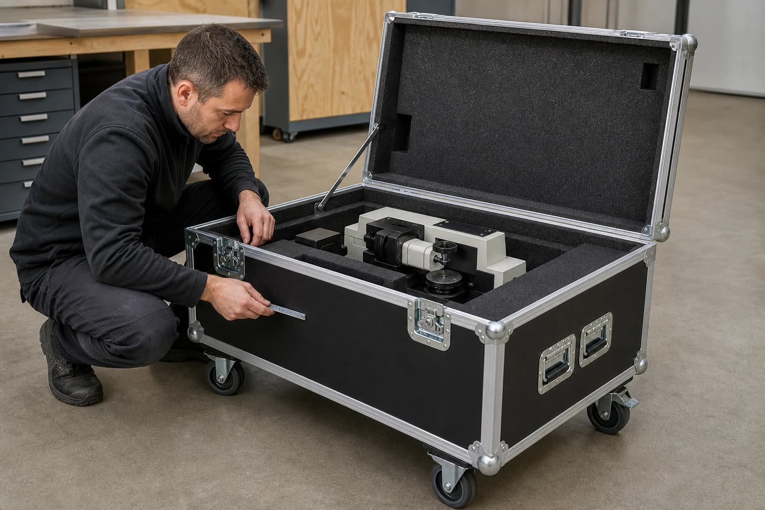
| Loaded-case first-article inspection | Use for every new case architecture and whenever the payload or loaded configuration changes. | Production-representative case carrying the complete payload, accessories, inserts and nominated service hardware. | Measure empty and gross mass, centre of gravity, closure compression, access, handles, casters and operating clearances. | Use the sample-case checklist tied to the case drawing, component list and payload revision. | Verify shell identity, panel build, installed BOM, payload inventory and measuring-instrument status. | Review closure, fit, balance, rolling, lifting access and any local panel or hardware movement after handling. |
| Buyer-defined handle/interface check | Use when the project requires a specific manual-lift or handle-interface observation. | Complete case with the selected handle combination and actual loaded mass or the defined representative load. | State lift direction, number of handlers, grip posture, load duration and any transfer aids or restrictions. | Follow the buyer's handling plan and destination ergonomics criteria, including loaded mass, handler count and transfer aids. | Inspect handle flange, backing, fasteners, local panel condition, centre of gravity and clear hand space. | Check operation, discomfort, permanent deformation, fastener seating, backing and shell condition after the lift sequence. |
| Buyer-defined caster rolling/obstacle check | Use when rolling, thresholds, ramps, turns or braking form part of the handling plans. | Fully loaded case with production casters, caster board, base frame and braking arrangement. | Define floor, option distance, speed, turns, obstacle/threshold, ramp, direction and braking points. | Use the project requirements map and nominated obstacle geometry rather than a universal rolling cycle. | Record wheel and bearing condition, fastener seating, caster-board integrity, gross mass and stability. | Inspect wheel tread, axles, brakes, mounting plates, base joints, looseness, tracking and tip tendency. |
| Buyer-defined latch, hinge and lid cycle check | Use when repeated access, lid retention or project-specific closure cycling requires supporting documentation. | Complete lid/base assembly with actual foam compression, mating profiles, latches, hinges and stays. | Define the project cycle count, opening angle, orientation, payload state and inspection intervals. | Follow the specified closure-cycle procedure for the selected hardware and complete lid assembly. | Measure alignment, joint gap, keeper engagement, fastener condition, hinge support and hold-open behaviour. | Recheck closure alignment, retention, looseness, wear, lid distortion, stays and any pinch or interference point. |
| Drop or impact option where applicable | Use only when the distribution assessment nominates a defined drop or impact method. | Complete loaded article representing production shell, payload, cushioning, closures and service hardware. | State orientation, mass, payload, conditioning, drop or impact sequence and acceptance criteria. | Name the exact ASTM, ISTA, ISO or ATA method, edition, project severity and any agreed variations. | Document shell, interfaces, foam, payload position/function, closures and pre-existing marks before the sequence. | Compare shell damage, joint movement, cushioning, payload contact and required function with the pre-test file. |
| Vibration option matched to distribution profile | Use when option hazards require vibration supporting documentation for a filled shipping unit. | Complete filled case fixed to the nominated fixture with actual or representative payload and restraint. | Define profile, axes, duration, fixture, payload, restraint, conditioning and distribution assumptions. | Record the selected ASTM, ISTA or ISO procedure, edition and project-specific vibration profile. | Verify fixture, article orientation, hardware torque/seating, payload position, foam contact and required function. | Inspect fasteners, extrusions, closures, foam set, payload migration/contact and specified functional checks. |
| Water/dust/IP option only when nominated | Use only when the buyer specifies an enclosure target and applicable complete-case method. | Complete enclosure with production seams, latches, hinges, seals, vents, cable entries and service panels. | State the target IP code, orientation, closure state, conditioning and every permitted penetration or configuration. | Name the IEC 60529 edition and exact test clauses or the separately specified project method. | Record complete enclosure configuration, seals, penetrations, internal indicators and pre-test function. | Inspect ingress indicators, seams, openings, hardware, internal condition and required function for that configuration. |
| Stacking option only when designed and nominated | Use only for a named case combination that the project intends to stack. | Selected upper and lower cases with production feet or dishes, support frames and representative loads. | Define case pairing, orientation, contact points, load, duration, environment and placement/removal method. | Use the specified stacking plan, load, duration and acceptance criteria for the named case combination. | Confirm identity, mating geometry, support condition, loaded COG, surface level and initial deformation. | Assess stability, engagement, local crushing, frame movement, residual deformation and safe separation. |
| Post-test case, payload and functional inspection | Perform after every specified conditioning, handling or transport test. | The same complete case and payload article identified in the corresponding pre-test record. | Preserve tested orientation and as-found condition until visual, dimensional and functional comparison is complete. | Use the post-inspection plan linked to the preceding test method, edition and acceptance file. | Retrieve baseline photographs, measurements, payload position, case condition and specified function from the pre-test record. | Compare shell, hardware, cushioning, payload contact/location and every nominated function; classify all change. |
What to check: Recalculate handle, caster, base, foam and handling demands against the revised mass distribution and fragility input.
What to check: Remap internal envelope, contact zones, insert geometry, closure, loading path and accessory restraint.
What to check: Measure actual thickness and recheck extrusion slot, machining, fastener coupon, shell mass and stiffness assumptions.
What to check: Recheck face/back balance, adhesion, cutting, sealing, hardware seating, cleaning and repair-material compatibility.
What to check: Trial straight and corner coupons for insertion depth, panel grip, end joints, mating closure and frame continuity.
What to check: Reopen cut-out, hole, edge-distance, backing, operation, closure-cycle and loaded-handling checks for the changed hardware.
What to check: Re-evaluate wheel reactions, base load path, rolling option, braking, stability and every permitted stacking pair.
What to check: Recheck material identity, fit, contact, clearance, recovery, conditioning and loose-part control around the payload.
What to check: Re-select method, edition, test article, load, axes/orientations, severity and acceptance criteria for the new option.
What to check: Compare materials, machining, assembly, hardware installation and production records on a new sample case.
| Issue | Visible sign | Likely cause | What to inspect | Practical response |
|---|---|---|---|---|
| Fastener pull-through or local crushing | Loose hardware, dished face or enlarged hole | Insufficient bearing, backing, edge distance or changed panel | Remove/inspect both faces and compare with interface coupon | Repair or redesign reinforcement and fastener option |
| Panel edge split | Visible split at drilling, extrusion or corner | Machining damage, weak edge zone or forcing into profile | Map crack, hole, veneer and extrusion fit | Replace part and correct machining/interface |
| Loose or separated extrusion | Gap, movement or missing frame continuity | Poor fit, fastener loss or impact | Inspect slot, panel edge and fastener pattern | Replace/reseat section and restore backing |
| Corner opening or loss of frame continuity | Misaligned junction or moving corner | Impact, incompatible hardware or shell distortion | Check geometry, corner hardware and adjacent frame | Rebuild junction and recheck square/closure |
| Latch misalignment or incomplete closure | Latch will not seat or lid compresses unevenly | Distorted shell, changed insert or hardware position | Inspect mating extrusion, payload/foam contact and latch mount | Restore the fit and mounting so the joint closes smoothly and evenly |
| Hinge/lid distortion | Lid binds, twists or over-travels | Unsupported hinge zone, stay error or impact | Cycle unloaded and loaded; inspect mount/backing | Repair the panel interface and align the selected hinge hardware |
| Handle pull-out or uncomfortable load path | Movement, local panel damage or unstable carry | Wrong location, inadequate backing or changed COG | Inspect handle interface and observe nominated handling | Redesign interface/handling plan |
| Caster-board damage or unstable rolling | Cracks, looseness, tipping or wheel misalignment | Concentrated reactions, weak board or unsuitable option | Inspect board/frame interfaces and loaded movement | Repair/redesign rolling base and select option |
| Foam bottoming, permanent set or poor recovery | Payload reaches shell or insert does not recover | Material, geometry, static load or conditioning mismatch | Inspect contact pattern and compare before/after condition | Replace/redesign insert and repeat nominated validation |
| Payload movement, contact or accessory escape | Scuff, shifted equipment or loose item | Insufficient restraint, clearance or compartment control | Inventory and inspect payload/insert contact | Correct restraint and fit; repeat handling/test stage |
| Cut-edge moisture entry or surface delamination | Swelling, lifted face or exposed core | Unsealed damage, incompatible repair or prolonged moisture | Inspect edges, repairs, surface and storage history | Dry, replace or repair with the compatible edge and surface system |
| Unstable stacking or impractical loaded handling | Case rocks, mates poorly or cannot follow option | Mismatched combination, COG or handling arrangement | Observe the specified pair or option with loaded mass | Identify it for individual storage or redesign the interface and handling plans |
Map cracks, dents, delamination, permanent bow and worn surfaces against the specified service limits.
Check exposed core, splits, moisture signs, coating continuity and every previous cut-edge repair.
Inspect profile straightness, joint gaps, movement, fasteners, mating surfaces and frame continuity.
Look for impact dents, elongated holes, lifted flanges, cracked panels and loss of flat corner seating.
Operate every latch and inspect keeper engagement, cup seating, fasteners, joint gap and compression uniformity.
Check grip, movement, flange seating, fasteners, backing and local crushing around every handle opening.
Inspect wear, looseness, opening angle, stay retention, fasteners, lid twist, over-travel and pinch points.
Inspect tread, bearings, brakes, swivel, fasteners, mounting plates, board cracks and loaded stability.
Check permanent compression, tears, contamination, looseness, contact marks, accessory control and closure fit.
Verify asset identity, readable labels, current drawings, service history, test scope, spares and open repair items.
Airline supplies and nominated repairable/expendable container projects
Performance testing of shipping containers and systems
Free-fall drop of loaded containers where applicable
Random vibration testing of filled shipping units
Procedure family selected for the exact test objective
General rules for compiling performance test schedules for complete filled transport packages
Conditioning plus vertical impact/drop option
IP Code for a complete nominated enclosure
Applicable operator, timing, technical documentation and reusable-packaging duties
Distinguish processed plywood from regulated solid-wood packaging components
Order chain, transaction documents, trademark permission and operator/importer role
Panel bond, use conditions and construction-product scope when the project invokes them
Before the purchase order
Flight cases commonly use lightweight poplar plywood, birch-faced combi constructions, all-birch high-ply panels, HPL-faced panels or phenolic-film plywood. The right construction follows the payload, case span, target empty mass, surface duty, extrusion slot, hardware reinforcement and repair plan. Send the case drawing and hardware schedule so the panel constructions can be quoted as a complete construction.
Poplar is often selected when low empty-case mass is the priority. Birch and high-ply birch constructions provide denser edges, higher stiffness and strong machining detail for demanding hardware zones. A birch-faced combi core can balance appearance, mass and price. Compare the complete face, core, ply build, actual thickness and surface rather than the species name alone.
Typical projects begin with the extrusion slot and the case span, then confirm the plywood build against payload mass, hardware cut-outs, reinforcement, cushioning and handling. Compact hand-carried cases may use a lighter construction; large touring or rolling cases usually need a stiffer panel and reinforced hardware zones. CUZI PLY can match candidate constructions to the supplied profile and case drawing.
Yes. HPL provides a broad decorative and wear-resistant surface range, PVC or other ordered laminates can support colour and cleanability requirements, and phenolic film offers a durable production surface. The quotation should identify the substrate, face/back balance, colour or texture, edge treatment, adhesive option and repair material so repeat orders remain consistent.
List each extrusion, corner, latch, handle, hinge, caster, rivet or screw by model, count and position. Add the actual panel thickness, cut-out sizes, edge distances, backing plates or washers and service access. A representative panel–extrusion–hardware sample confirms machining quality, seating and clearance before the full case is built.
Start with the payload geometry, mass distribution, fragile faces, permitted orientation, connector access and no-contact zones. Then state the foam or insert material, density or firmness option, thickness, geometry, adhesive and replaceable sections. The loaded case should close without unwanted compression and maintain clearance after the chosen conditioning and transport checks.
Yes, when the buyer identifies the relevant ATA Spec 300 Revision 2020.1 scope, container category and airline-supply or repairable-item application. The specification package should name the payload, case configuration, maintenance plan, test methods and required documents so the completed case can be assessed for that project.
Use the actual distribution transport and handling hazards to select the test. Record the named ASTM, ISTA, ISO or customer method, edition, conditioning, filled test article, payload, orientation, severity or vibration profile and acceptance checks. This produces a test programme that represents the shipment rather than a generic demonstration.
An IEC 60529 IP assessment applies to the completed enclosure. The target therefore includes the lid/base joint, seals, latches, hardware recesses, vents, cable entries and service panels together with the plywood shell. Provide the required IP code and use condition so the enclosure details and test methods can be planned together.
Provide payload drawings, dimensions, mass, centre of gravity, fragile zones, accessories, external case envelope, opening method, panel and surface preference, extrusion and hardware schedule, cushioning, handling and transport lanes, test target, reuse plan, quantity, destination and target date. CUZI PLY will return a recommended panel construction, thickness option, surface option, packing basis and quotation.
Product: Flight Case Plywood · Destination: provided with the inquiry · Shipping basis: Recommended from order quantity and destination · Reply: [email protected]
Plywood enquiry
Send the payload drawing, case envelope, panel and surface preference, extrusion and hardware schedule, cushioning, handling and transport lanes, required tests, quantity, destination and target date. We will recommend the construction, thickness option, packing basis and suitable trade term.
CHAT WITH CUZI PLY↗